Court-Zee Engine
Here's a twin flywheel mill type horizontal engine that uses a single crank throw.The crank pin (.125 ") is pressed into the right flywheel......flywheels are pressed onto a main shaft (also .125"). Main shaft rides on a brass hex post that forms the main bearing (two small washers keep the flywheels from dragging against the post). The main crank throw (about 5/16 ") carries the piston connecting rod and the valve push rod. Valve pushrod operates a rocker arm that pivots on an 8-32 screw attached to the top of the block. Opposite end of rocker arm controls the valve (made from a drywall nail......the head was shaved down to .125" and the pointy end was peened flat and drilled about .075"). Intake is via a hole on the left side of the block (not shown in top picture). Layout is similar to other mill engines on these pages, except valve moves vertically instead of horizontally. Piston is .187" brass and con rod is coat hanger wire. Two dimples on top of block are mistakes (!?!?). Valve motion for this design was barely enough because pivot point was too close to valve. Our second version of this engine moved the pivot point about .25" to the left (closer to the flywheels). Worker better as a result.
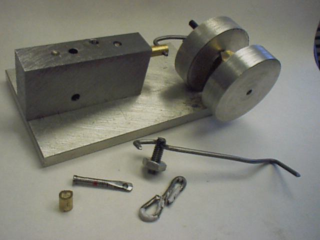
Second photo shows partly dissembled engine. Intake hole (for compressed air) can be seen on side of block. Items in front of engine are: 1) short piece of plastic tube to retain rods on crank: 2) valve (built from drywall nail): 3) short valve rod (coat hanger wire): 4) rocker arm and pivot assembly (built from coat hanger wire and 8-32 screw). Plans at bottom show air inlet at front instead of side. Most dimensions on plans are approximate.