Mark-Zee
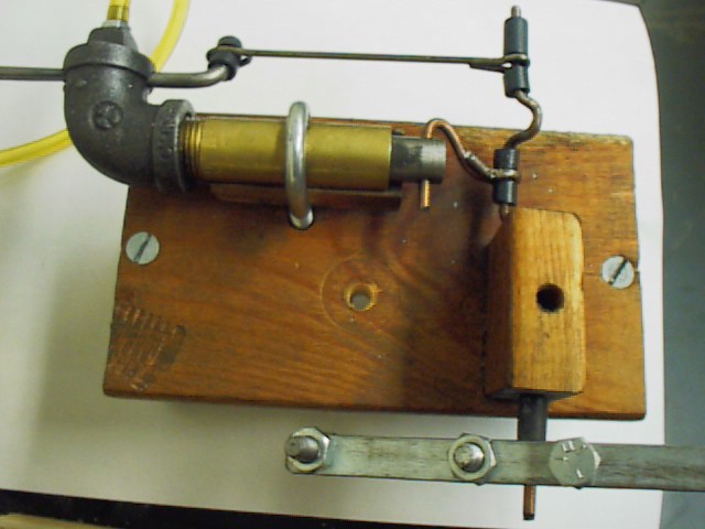
Here's a "plumber's nightmare"......a steam engine built (mostly) from plumbing parts and scrap wood. Cylinder is brass pipe with iron elbow and plug. Cylinder is held fast using U-bolt......sits on wooden spacer sanded to match OD of cylinder. Base and main bearing are wood. Crank and rod are .125 copper coated welding rod. Valve control rod (push rod) is coat hanger wire. Piston throw is about .375. Valve throw is about .187. Crank throws (piston and valve) are about 90 degrees out of phase. Valve is .187 steel (I used an old welding rod with the flux scraped off). Air inlet hole (.089) is drilled through plug (that's where the hose is attached in the picture). After plug is tightened into elbow, .187 "valve-sliding" hole is drilled through elbow and plug. Valve has .089" inlet hole and "ground flat" (for venting). Piston is turned steel. Flywheel is two plates bolted together to pinch crank. A kink may be added to push rod for valve timing adjustment.
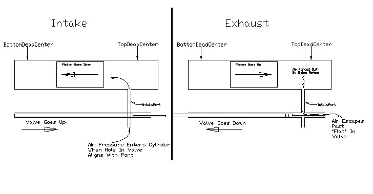
The picture below gives a pictorial idea of the valve operation.