McCabe's Runner-
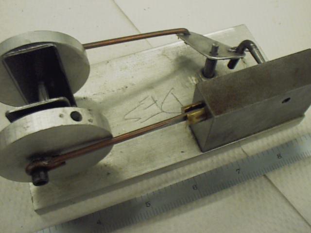
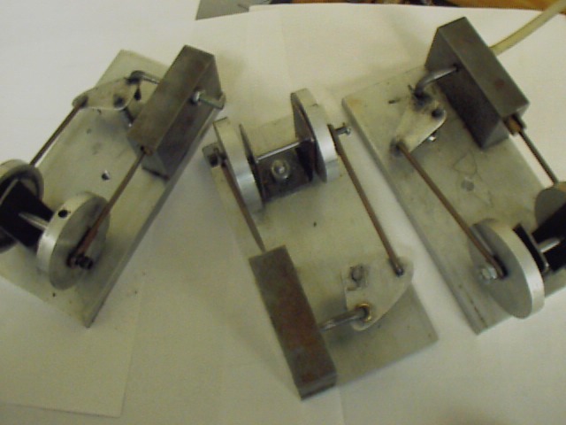
This was named by my students (so don't blame me!). This particular example has run (on about 10 psi of air) in a promotional display (for our program) for probably about a hundred hours. Detailed plans are at bottom of page. I designed this engine based, very roughly, on a set of plans in an old book called "The Boy's Book of Motors, Engines and Turbines" (written before the days of equal opportunity, I suppose). We've made dozens of these (at CCM) in the past 4-5 years (including some "left handed" ones and "twins"). Valve is a common nail, rods are 1/8 welding rod, rocker arm is 1/4-20 bolt with head cut off and wrist pin is paper-clip wire. Hole on right side of block (first photo) is "intake port" were compressed air is applied. Holes in rocker arm should all be about .125~.160 (the plan sheet is wrong). Bearing carrier can also be built from solid aluminum instead of sheet steel. Wood base works just as well as the aluminum. Occasionally, we fill the big end of the connecting rod with melted solder (or brass) and then drill it out to fit the 8-32 screw; sort of like an old time poured bearing. This semester we built one that ran all day on 3 psi (the builder really took his time with fits and clearances). First photo is close up of typical engine......second photo shows three engines recently built.
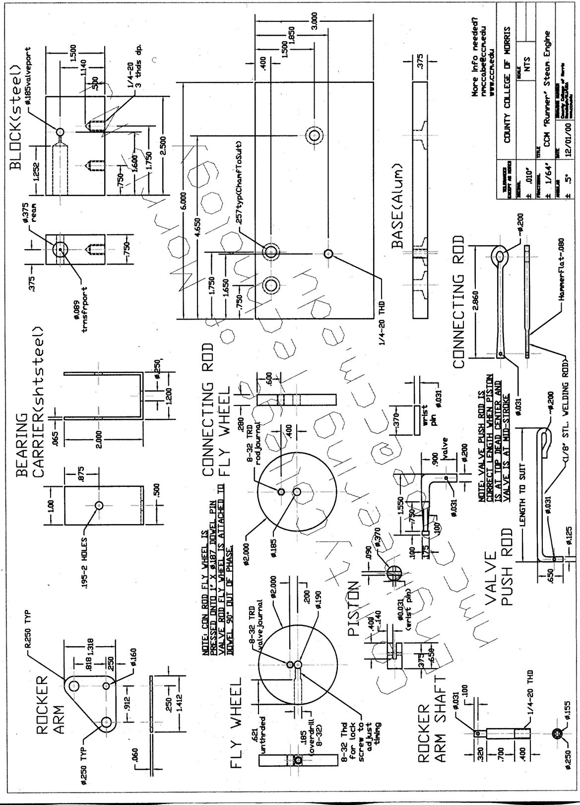
For a page with better resolution of this print-Click Here
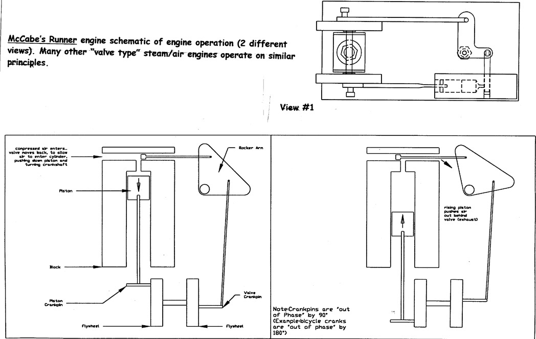
For a page with a schematic explaination of the Runner engine-Click Here