3 Sisters Engine
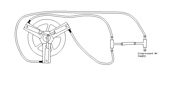
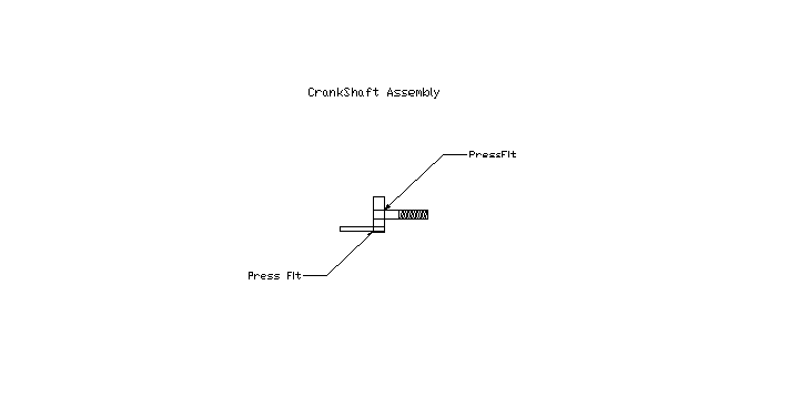
Here's an interesting 3 cylinder oscillating-type engine that we made using modified plans from the Jingle Bell Motor (seen elsewhere on this site). The most difficult-to-build part might be the CNC-produced flywheel (but a simple round one of the same diameter and built from plywood, would work fine......there's also a "straight-bar" alternate flywheel shown among the drawings below). The two "T" connectors and plastic hose are aquarium supplies. Crank is pressed together (you can slightly "under drill" (by about .001" or .002") the holes and press the main shaft and crank pin into place using a good vise (or an arbor press, if you have one). Drill or ream the cylinders to a very smooth .25 diameter. Turn down the brass pistons to about .260"..........then use a file or emery paper on a lathe to finish them to size, using one of the cylinders as a gauge (when the piston just fits, you're done). This finishing process is best done on a lathe, but I've successfully done it by chucking the piston into an electric hand drill.
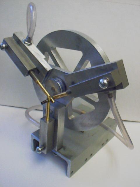
(Above) Pistons are "staggered", one behind the other. This is possible because each of the cylinder "Standards" has a different step at it's attachment point to the main bearing.
(Above) Engine is mounted on channel aluminum (anything similar would work fine).

(Above) "Rear" view, showing hose "T" connectors and flywheel. Flywheel is held between two nuts, and is easily removed. The small hole in the back of the Standard (seen in the right side of the picture)is the exhaust port. The larger hole near it is the 10-32 threaded hole for the pivot bolt.
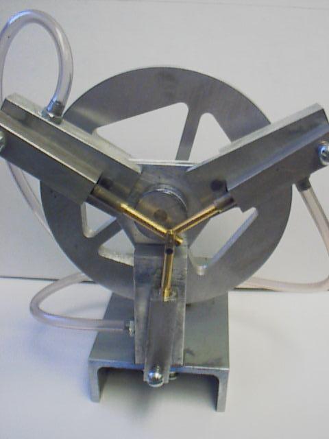
(Above) General Layout of engine. Once broken in, the motor should be able to run on just one cylinder.


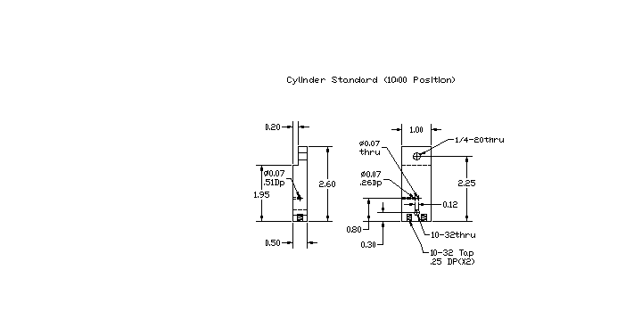
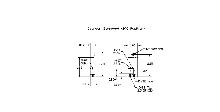
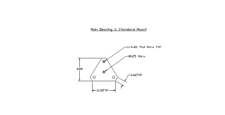
The cylinder "Standard" is the mount for the cylinder. It also contains the valve porting. There are three different Standards....all are identical except for the step on the main bearing attachment area.
Note concerning the two 0.07" holes in the right side drawing above. The hole on the right is "thru"....this is the exhaust port. The hole on the left is ".26 deep". It intersects another 0.07" that is drilled in from the side (and is .51 deep). These two intersecting holes form the intake port. The side hole (the one that is .51 deep) should be tapped 10-32 at it's "mouth". This is where the air supply connectors thread in. This standard is the 6 O'Clock Standard (the lowest one). It has two threaded holes for mounting to the base. The other two Standards (shown below) are similiar.
The following two drawings (of Standards) are identical except for the step.
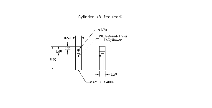
(Above) Cylinder is built from 1/2 by 1/2 square aluminum. The 0.20" hole is the pivot hole.
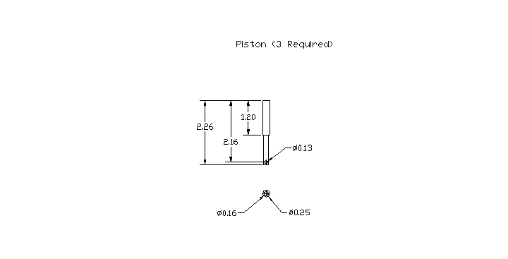
(Above) Piston is built from brass.
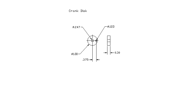
(Above) Crank Disk is built from aluminum.
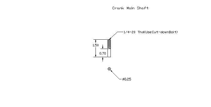
(Above) Build main shaft from 2" long 1/4-20 bolt.
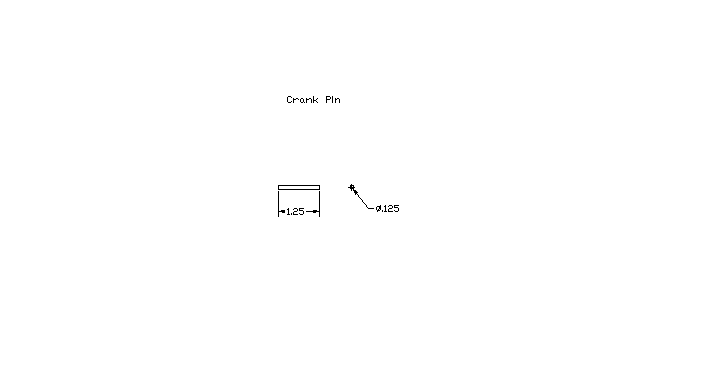
(Above) 1/8" steel dowel pin works best here. It can be cut down to a length of about 1.0" when the motor is all finished.
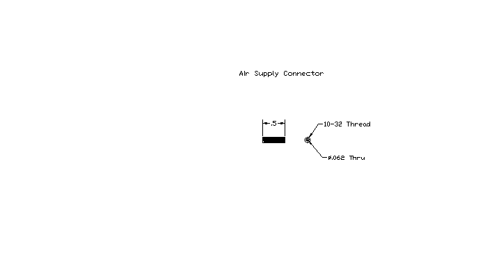
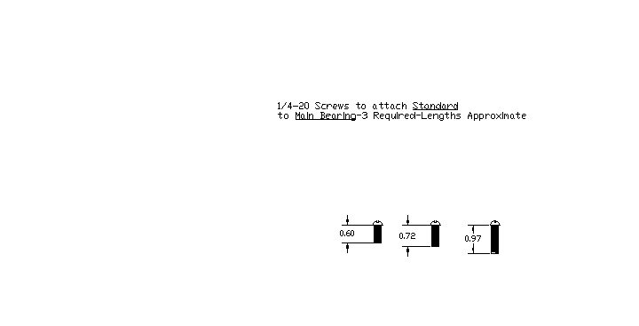
(Above) Build these from cut-down 10-32 machine screw. Drill a .062" hole through center. Use aquarium hose (or similar) that will just slip over the thread.
(Above) Built from 1/4" aluminum plate stock. Try not to make center hole too loose.
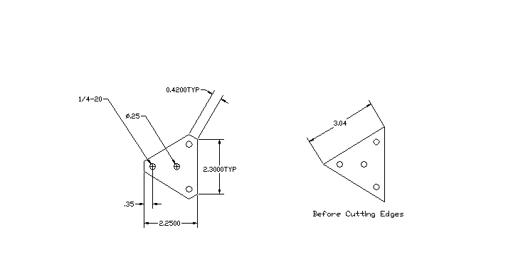
(Above) Size before being built shown on right.
File or sand these down to length after they've been installed.

(Above) Adjust the screw tension so that the cylinder will slide easily across the Standard. I lapped these parts together (with toothpaste); then clean and lightly oil.
(Above) The flywheel is "trapped" between two hex nuts on the threaded end of the main shaft. When fitting the crank through the main bearing, use two small flat washers; (with 1/4 " ID hole) one on either side of the main bearing plate.
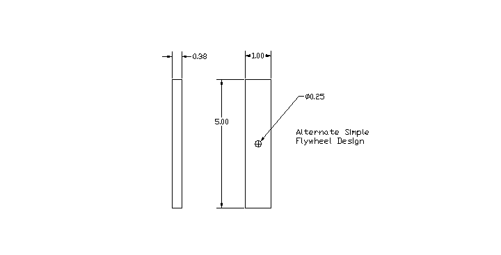
(Above) An alternative to the CNC flywheel. Doesn't look as nice but works just as well.

Engine will self-start most of the time. Runs nicely on about 10 PSI.
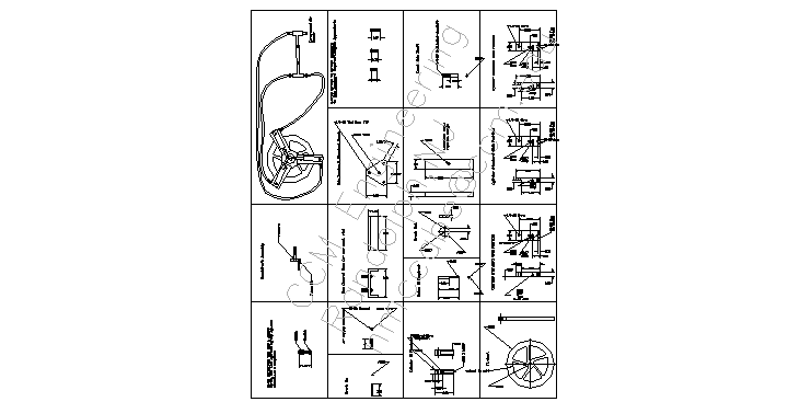
Full Page of Plans: All Plans above, on one page (may be a bit "cluttered"