Paul-Zee
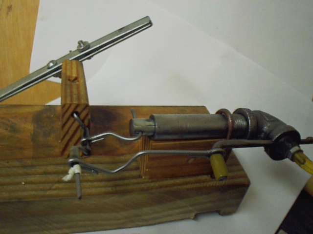
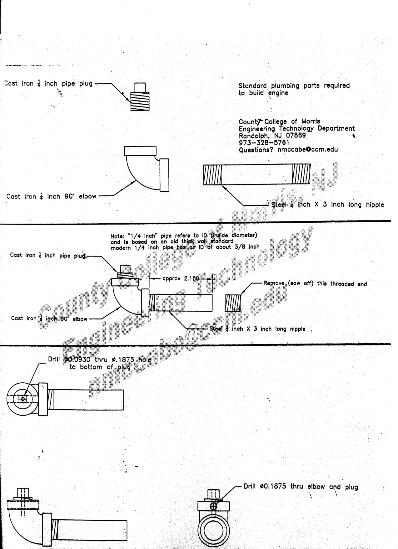
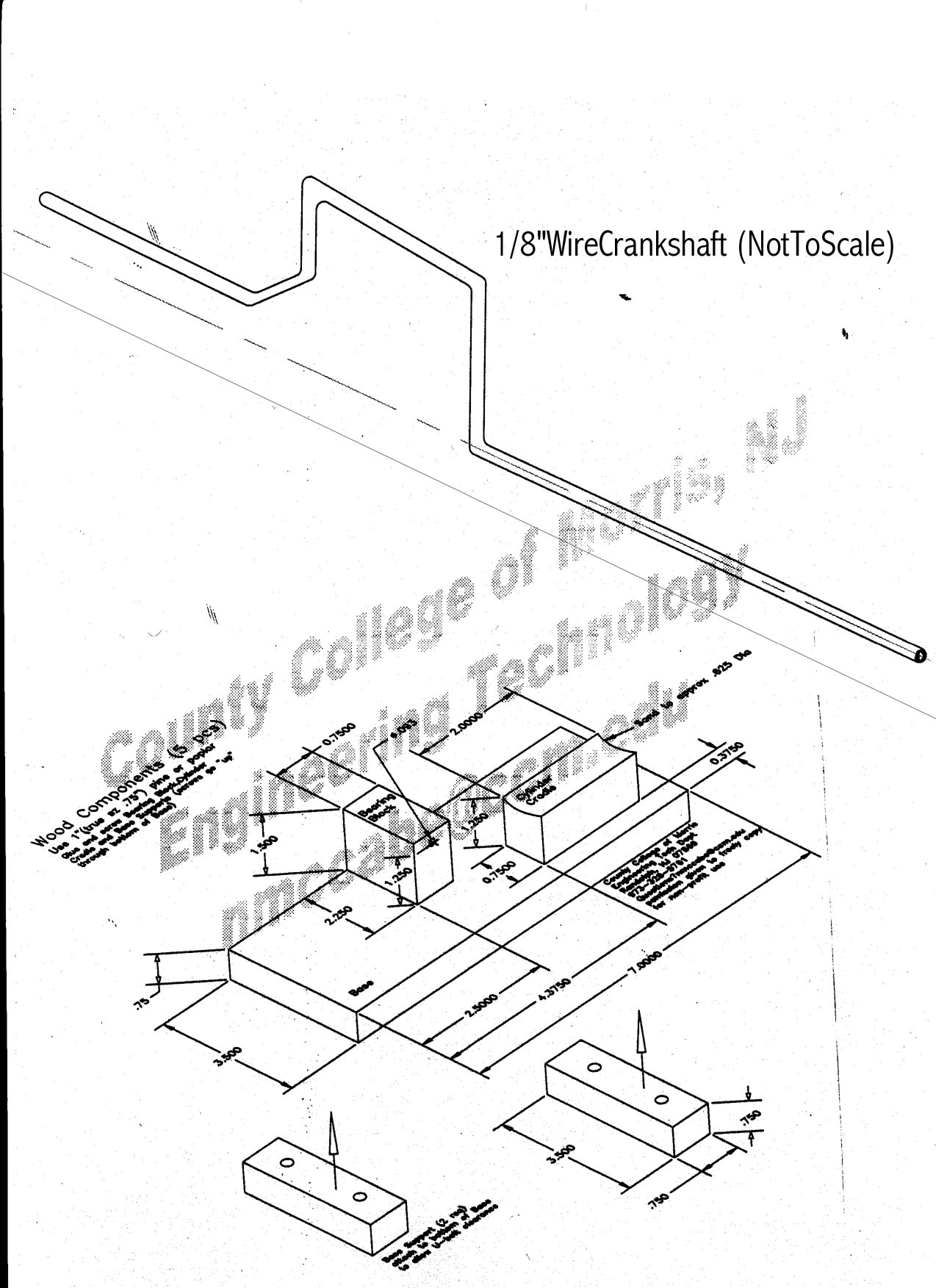
This is a smaller version of the "Mark-Zee" engine. Built with no machine tools......just hand tools and a 3/8" electric hand drill. Plumbing is "1/4" pipe. Crank and rods are coat hanger wire. Flywheel is 2 flat steel strips, bolted together (and pinching crank). Valve is 3/16" steel rod with small through-hole and hand-filed "venting flat". Base, main bearing and cylinder cradle are scrap wood. Cylinder U-bolt is made from 1/8" welding rod (threaded at ends). Piston is cut from a long 5/16 bolt (it was "turned down" by holding a file against it while it spun in electric hand drill). Steel pipe cylinder was "honed" using an electric hand drill and a 1/4" wooden dowel that had a piece of sandpaper taped to one end. Kink in valve push rod is for valve timing adjustment. Push rod retainer on crank is a "twistee-tie"(?!). Added notes for construction: Through hole (in 3/16" valve) is 3/32" or roughly 0.093"...a standard drill size. The "hose connector" is threaded into the cast iron pipe plug. You must drill the pipe plug with a 5/32" drill and tap it using a 10-24 tap. You only need to tap the hole about 1 or 2 turns...just enough to allow the connector to "catch" a thread. The "hose-connector" is a 10-24 screw with a small hole drilled thought it (it's like a small piece of threaded pipe). To make this part, hold a 10-24 by 1" long machine screw in a vise (holding on it's head...don't worry about damage to the head.....you're cutting it off anyway). drill into the screw using a 1/16" drill bit )or maybe a 3/32" drill if you have trouble breaking bits)...use a hand drill at slow speed. Don't have to go very deep....1/2" to 3/8" is plenty.....don't have to be perfectly centered. Cut off drilled part of bolt and use a 10-24 nut to lock it against cast iron pipe plug. You only need to thread it into the pipe plug about one turn. There should be enough of a stub extended to slip a piece of plastic tubing over. Most difficult part of this engine is making crank with correct bends.....I usually make 2 or 3 before I get one right. If it's built correctly, the valve through-hole will align with the air inlet hole (in the cast iron plug), *just* as the piston is at mid-point (half-way down the cylinder). I usually assemble it without the valve through-hole...turn it so that the piston is at mid-point, and mark the position of the valve through-hole by sticking a small sharp scriber into the 10-24 threaded hole. The "flat" on the valve must be very close to this through-hole...only about 1/16" apart....and the valve flat must have a sharp "step" between it and the through-hole (don't taper the valve flat into the valve through-hole)....make it a distinct step, as shown in the bottom picture. Parts must spin freely...if you give the "flywheel" a spin with your finger, it should keep going several turns before stopping. Use plenty of light oil (3-in-1 is good) when first trying to run it. I use about 10 psi air pressure. Should run anywhere from 5 psi to 30 psi.
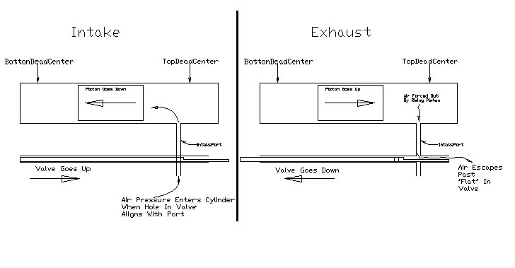
The picture below gives a pictorial view of the valve operation.