Spridget Front Suspension Tube Shock Conversion
The following information is for reference only. The author does not propose to encourage any individual to duplicate this process. Persons wishing to modify their cars in a similar manner should know that this work has not been certified by any professional engineer as safe or appropriate for Sprite/Midget vehicles. It is possible that under certain circumstances, improperly modified suspension parts could suffer catastrophic failure causing serious personal injury. Also, automotive coil springs may be held or mounted under high compression and may be dangerous. This site is simply a documentation of personal efforts to modify a particular vehicle.
_____________________________________________________________
Spridgets use a rather outdated form of dampers called "lever-arm dampers". Note that dampers are generally referred to as "shock absorbers". Actually, the coil (or leaf) springs absorb shock; the dampers dampen oscillation. Nevertheless, since dampers are generally called "shocks", that's what we'll call them too.
Many of the tube shock kits sold for the Spridget are intended for racing. Typically, the lever shock is replaced by a fabricated upper control arm attaching to the top of the king-pin. The design shown here leaves the lever shock in place. It continues to act as the upper control arm. The lever arm shock valve is disabled so that no dampening action occurs through the lever.
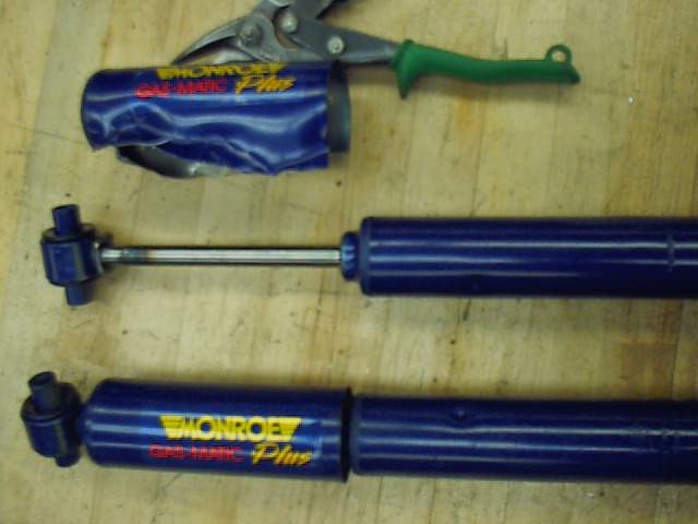
Parts fabrication for this modification involved three main pieces. It also required the modification of the Monroe shocks that were used. These Monroe Road Sensor shocks are part # 5877R. This modification involves removal of the dust cover. These 4 primary parts are seen below:
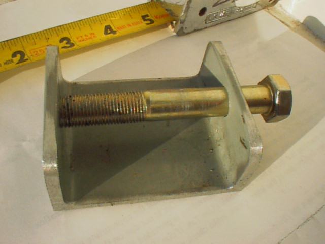
1. Upper shock mount built from aluminum channel stock (or similar). Right side (in photo) is drilled 1/2". Left side is tapped 1/2"-20. The 1/2" bolt shown will go through the upper shock grommet and a 1/2"-20 nut will be tightened against the outside of the mount to prevent the bolt from turning (see photo below):
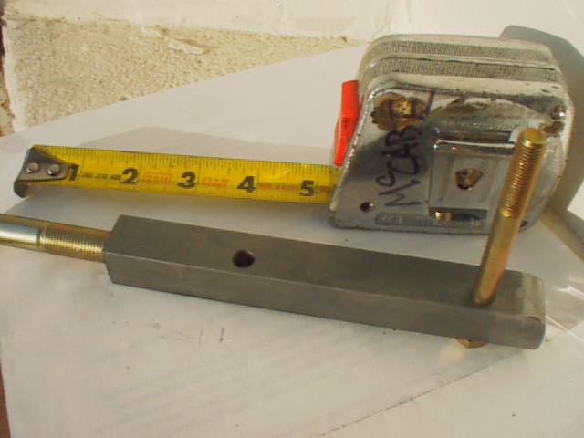
2. Lower shock mount built from 3/4" X 3/4" mild steel cold rolled bar stock. Left side (in photo) is tapped 1/2"-20 for lower shock grommet bolt. Two (slightly offset) 5/16" holes are drilled to attach this part to lower control arm (see photo below):
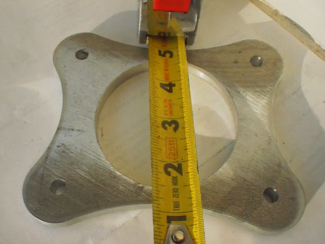
3. Lower shock mount base plate. The plate picture was built from 3/8" aluminum plate, but 1/4" or 3/8" steel might also have been OK. The fancy outer shape was just for appearance and was cut on a CNC mill. A rectangular plate would have worked just as well. The large center hole is need to install 1/2" tall spacers between the plate and the spring seat. (see photo below):
4. Modified Monroe Shock Absorber (with dust shield removed on the upper shock in the photo seen below). These shocks are original equipment on the rear or 1984 Dodge Colts (and similar Mitsubishis)and are part # 5877R. Dust shield removal required four cuts across the top of the shield with a hack saw; then the shield was cut off with aviation tin snips. Be careful not to scratch or cut the polished shaft. The end tubes (mounted in the rubber grommets) should be carefully drilled to 1/2" (this will remove only about .016" of material):
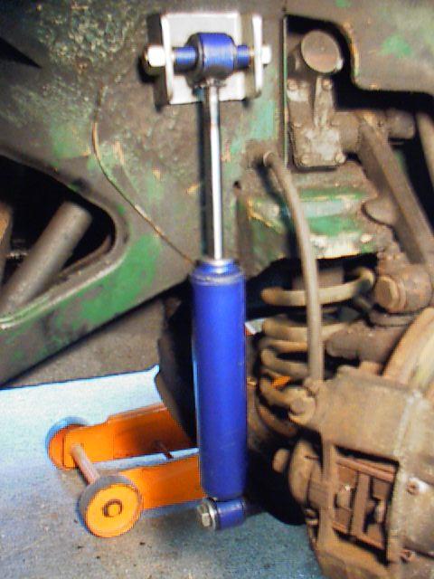
A general picture of the shock setup can be seen below with the tube shock mounted rearward of the main suspension components. The upper shock mount is held in place with two 1/4"-28 bolts (and nuts). The two 1/4" holes drilled in the car for this purpose are the only permanent modifications required for this conversion. 1/4" stainless steel fender washers are used to help secure the engine-bay side of the 1/4"-28 bolts (PL200 construction adhesive should be used to prevent "creep" of components...this is an excellent product for use in all similar applications). For added strength or security, a piece of 2" steel plate (1/8" thick) could be substituted for the washers (with appropriately spaced holes).The position of these holes can be determined by mounting the shock on it's lower mount first. Make sure drilling is done in the "double thick" area. This is a structural reinforcment area to the upper spring seat; it is .155" thick, and should be well capable of managing loads for the upper shock mount (for reference, the factory lower "A" arm mounts are located on .093" steel and these mounts carry far higher loads). Be sure the car is jacked off the ground, with the suspension hanging free. Compress the shock about 3/4" (from maximum length) before marking the position; this will prevent the shock from "topping out" when the car is jacked up off the ground:
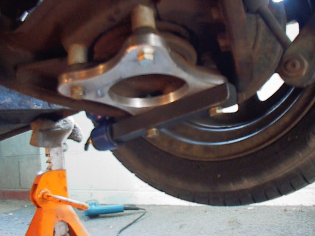
A bottom view (looking up at the lower control arm) is shown below. Note that in this application the spring seat is spaced away from the lower control arm with an extra .75" tall spacer (with 5/16" hole); this has the affect of lowering the car about 1.25". The two 5/16" mounting bolts for the lower shock mount are about 3/4" longer than the other two bolts that hold the aluminum base plate in position. In order to prevent distortion of the stamped steel spring seat (when tightening the four bolts) , there are 1/2" tall spacers (with 5/16" hole) positioned between the aluminum base plate and the seat. These four spacers are not visible in the picture; the large center hole in the base plate is needed to position these spacers. Also, note that the lower leading edge of the shock mount has been radiused on a grinding wheel.Note regarding shock mount: various conversion kits mount the shock to the leading edge of the "A" arm using the sway bar mounts. This may cause a twisting moment that could cause the arm to crack or fail (Spridget "A" arms are fairly fragile and may crack under ordinary use with enough time/mileage). The method shown here places the shock load near the center of the "A" arm (in an attempt to reduce the moment arm affect). Under no circumstances should additional holes be drilled in these "A" arms...the work-hardening effect of the stamping process used to build them, makes them unsuitable for additonal drilling. Even if your Spridget is unmodified, check the lower "A" arm for cracks regularly (especially near the lower pivot).
General dimensions for the 3/8" thick aluminum lower backing plates are seen below. The 0.316" holes are cut with an "O" drill and allow some "play" for assembly. A simpler version of the plate is illustrated on the right.
![]()
The 3/4" X 3/4" mild steel lower shock mounts are seen below (Front and Bottom side views). Note that the 5/16" holes drilled through the mounts are offset and not on the center line of the part (in the bottom view, they are .250" from the right edge). This allows a small amount of needed clearance that moves the lower part of the shock away from the caliper at full steering lock (the "thicker" side should be away from the caliper). The 1/2"-20 holes are 1.75 deep. The 1/2" mounting bolts that thread into these holes should be purchased extra-long and then cut down so that they *just* bottom out with enough clearance to hold the lower shock grommet with no excessive play.
![]()
A schematic of the arrangement for bolting the lower base plate, shock mount and spacers is shown below. This view is looking from the rear of the car at the left side suspension. Note the "offset-in" of the lower shock mount. Obviously, this is not to scale and is only provided for visual clarity.
![]()
For final assembly, grease 1/2"-20 shock mounting bolts. Test clearance of shock to caliper and tire on the ground, with car raised and with a load on the front fender (it is fairly close with this setup). Lower shock bolts should not be over-tightened (since threads in lower shock mount are hand cut) and should be safety-wired (drill a 1/16" hole through bolt head for this purpose). Upper shock mounts should be carefully tightened so that upper mount is not bent in or deformed. Be sure lever shocks are filled with oil (to prevent seizing) but disable valve. Be sure toe-in is set correctly. Since this car was lowered, bump-steer had to be adjusted. To adjust bump-steer so that it is "in the ball park" , raise steering rack so that it has been elevated equal to the amount the car was lowered (i.e. If the car has been lowered 1", raise the rack 1"). These modifications were done on a car that had a recently-rebuilt front end, with new king pins, king pin bushings, teflon control arm bushings, etc. Any modification similar to the one outlined above would always include a renewal of the various suspension components subject to ordinary wear and tear.