Tom-Zee
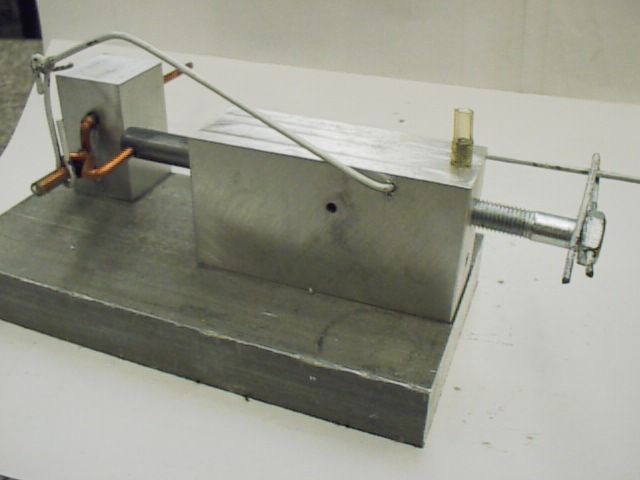
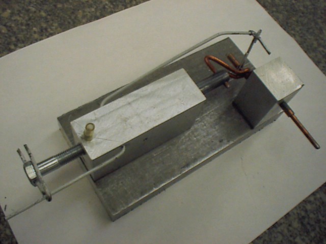
Here's an engine with a "one-throw" crank and an unusual intake system that uses a 5/16-18 bolt to supply air. An 1/8" hole is drilled up through the threaded portion of the bolt (so that the bolt is partly hollow). A 5/16-18 threaded hole is placed at the top of the cylinder (where a spark plug hole would be in a gas engine). An air supply hole is drilled through the top of the block (it's on the left side of the top photo......there's a short piece of hose attached to it). The air supply hole cuts into the 5/16-18 threaded hole. A short push rod is connected to the main crank throw. The opposite end of this rod is connected to the long rocker arm. Both the rocker arm and the push rod are built from coat hanger wire. The rocker arm "twists" the bolt back and forth as the engine turns (by means of a connecting link drilled through the bolt head). A short hole is drilled through the side of the bolt. When the piston is in the correct position (middle dead center), the bolt twists so that this short hole is aligned with the air supply hole. For exhaust, two vent holes are drilled in the block......these vent holes are exposed when the piston reaches bottom dead center (similar to the exhaust on a 2 cycle engine). Oddly, when we plugged one of the vent holes, the engine ran better. Flywheel is two flat strips that pinch the crank (not shown in photos).